round button
Contact Us Now

HUAWEI Radio Link Microwave Transmission System OptiX RTN 950A

The OptiX OSN 580 is a packet- and TDM-oriented new-generation multi-service optical transmission system, which is positioned at the convergence layer and access layer among Huawei's end-to-end Hybrid multi-service transmission platform (MSTP) product se

Consult
HUAWEI Radio Link Microwave Transmission System OptiX RTN 950A

Product Description


  • The OptiX OSN 580 is a packet- and TDM-oriented new-generation multi-service optical transmission system, which is positioned at the convergence layer and access layer among Huawei's end-to-end Hybrid multi-service transmission platform (MSTP) product series. This system is characterized by its large capacity, high availability, low power consumption, and compact structure.
  • The OptiX OSN 580 supports multiprotocol label switching transfer profile (MPLS-TP), pseudo wire emulation edge-to-edge (PWE3), Ethernet, WDM, SDH, and PDH technologies. With these technologies, a pure TDM network, pure PTN network, or Hybrid network can be provisioned.
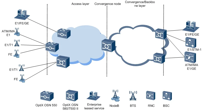
  • As the convergence layer and access layer equipment, the OptiX OSN 580 is networked with other OptiX OSN equipment to provide a complete solution covering the backbone layer, aggregation layer, and access layer. The complete solution meets 2G/3G/LTE base station backhaul and enterprise leased service access demands. Figure 1illustrates the network application of the OptiX OSN 580. 
Figure 1 Network application of the OptiX OSN 580


Product Features


Large Capacity, High Availability, Low Power Consumption, and Compact Structure

The OptiX OSN 580 is a device used at the access and convergence layers, which features large capacity, high availability, low power consumption, and compact structure. The OptiX OSN 580 supports:

  • A maximum of 280 Gbit/s packet switching capacity, a maximum of 280 Gbit/s TDM access capacity
  • 1+1 protection for system control, switching, timing, and power supply units, and network-level protection such as MPLS-TP APS, Ethernet ring protection switching (ERPS), link aggregation group (LAG), multi-chassis link aggregation group (MC-LAG), link-state pass through (LPT), subnetwork connection protection (SNCP), and multiplex section protection (MSP)
  • A maximum power consumption of 1600 W, and a typical power consumption of only 668 W. The equipment is energy saving, which help reduce customers' OPEX
  • Both the DC-powered and AC-powered models of the 5U compact chassis can be easily installed in an ETSI or 19–inch cabinet.

Universal Switch Architecture and Multi-service Transmission

The OptiX OSN 580 has a universal switch architecture, as shown in Figure 1. The OptiX OSN 580 supports coexistence of the time division multiplexing (TDM) domain and packet transport network (PTN) domain, which achieves smooth evolution from the TDM domain to the PTN domain while allowing the on-demand configuration and application of pure TDM services and packet services.
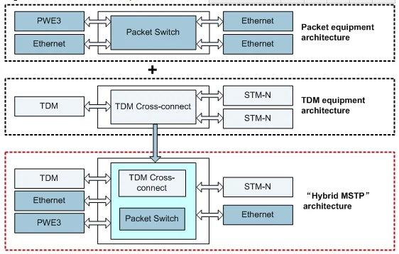
Figure 1 Architecture of the OptiX OSN 580 

The OptiX OSN 580 supports the access and transmission of PDH, SDH, Ethernet, and MPLS-TP services.

In the PTN domain, the OptiX OSN 580 performs highly efficient statistical multiplexing of data services to reduce the service transport cost per bit. In the TDM domain, the OptiX OSN 580 incorporates SDH functions to ensure the high transport quality of Native TDM services (mainly voice services).

Super Bandwidth and Multi-service Transmission Provided by Smart Line Boards

The OptiX OSN 580 supports switching of packet and VC granular services to address the requirement on transmitting SDH and packet services at the same time. The OptiX OSN 580 uses smart line boards so that:
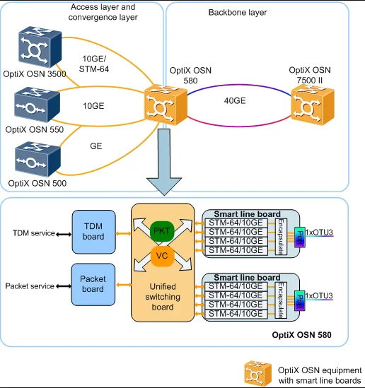
  • A maximum of 40 Gbit/s hybrid services can be transmitted over a single fiber, greatly improving network bandwidth and implementing flexible grooming of large-granularity services.
  • SDH and packet services can be transmitted at the same time to save optical fiber resources.
  • Services can be easily adjusted. Smart line boards support SDH and IP services, allowing a smooth upgrade from the TDM domain to the IP domain. For example, when a 10G SDH service and a 10G packet service evolve to a 20G packet service, boards need not be replaced.
Figure 2 Solution Using Smart Line Boards 

End-to-End Service Configuration, One-Click Commissioning, and One-Click Fault Locating (TP-Assist)

Compared with legacy TDM networks, PTN networks have the following characteristics in terms of O&M:

  • Lack of overheads indicating the physical states of networks. When a fault occurs on a PTN network, no visual and fast indicator is available to locate the fault.
  • Networking diversity and complication, which require powerful O&M capabilities.

To address those issues, the equipment uses the TP-Assist to provide more O&M means and simplify O&M operations for PTN networks during installation, commissioning, service configuration, fault locating, and routine maintenance. With the TP-Assist, PTN networks have the SDH-like O&M capabilities, which reduce the technical requirements for O&M personnel and improve O&M efficiency.
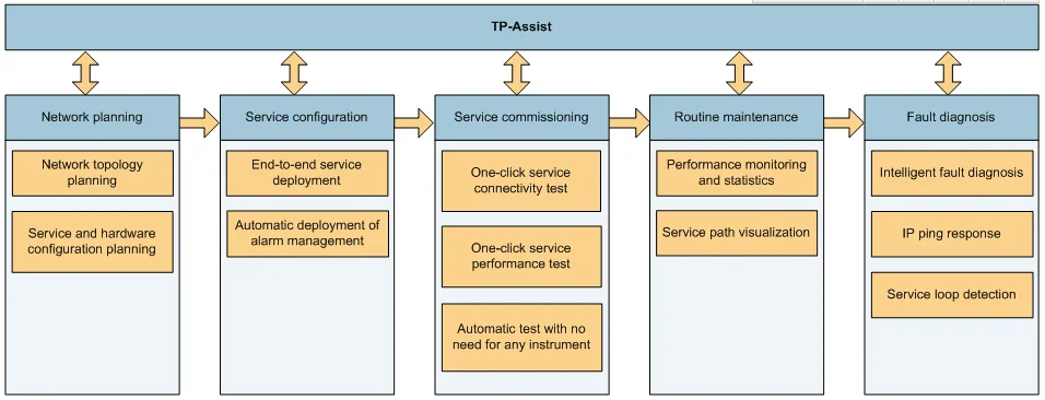
Figure 3 TP-Assist 

Hierarchical OAM

The OptiX OSN 580 supports the hierarchical OAM functions and have the SDH-like O&M capabilities. It can quickly detect and locate faults at each layer.

The hierarchical OAM functions include ETH OAM and MPLS-TP tunnel/PW OAM. Figure 4 shows the application of hierarchical OAM.
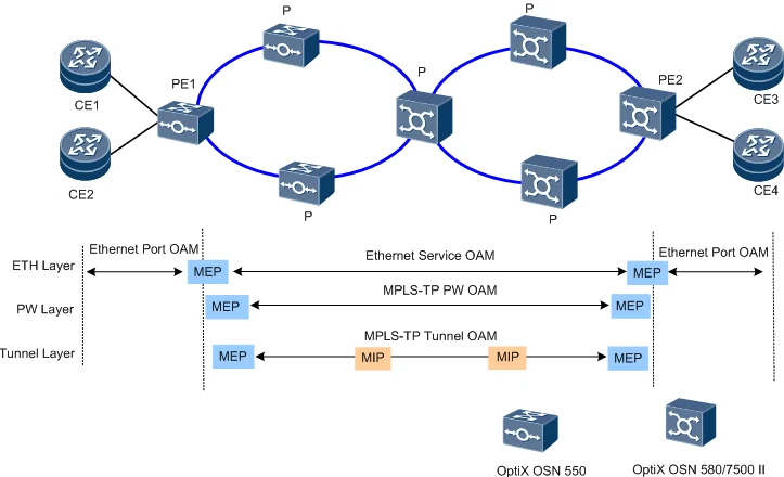
Figure 4 Application of hierarchical OAM 


Specifications


Item Description
Appearance

Chassis Dimensions (H x W x D): 221 mm x 442 mm x 224 mm

Board
  • System control, switching, and timing board: UCX
  • Packet processing board: EM20
  • Hybrid line board: HUNS3 and HUND2
  • SDH boards: SL1Q, SL4D, SL41O, SL16Q, SL64S, and SL64D
  • PDH boards: PL3T and SP3D
  • MDM boards: DMD2 and MR2
  • Auxiliary boards: AUX and FAN
  • Power supply boards: APIU and PIU

For services and ports supported by the preceding boards, see Table 1.

Packet switching capacity 280 Gbit/s
TDM access capacity 280 Gbit/s
Equipment-level protection
  • 1+1 backup for power supply
  • 1+1 backup between active and standby system control, switching, and timing boards
  • Fan protection (The failure in a single fan does not affect the operation of the other fans.)
Intelligent fan speed adjustment Supports the automatic adjustment of fan speed based on the highest temperature of the board in the chassis.
Management ports and auxiliary ports Interface Type Description Connector
External clock port 120-ohm external clock port, which can work in 2048 kbit/s mode or 2048 kHz mode RJ45
Power supply port Power supply port connecting to two -48/-60 V DC power supplies 2 mm HM connector
Two 110 V/220 V AC power supply ports Three-phase socket
Network management port Ethernet NM port/NM cascading port, which is connected to a network management system (NMS) RJ45
Alarm input/output port 6-input/2-output alarm port RJ45


Service Board/ Port
Board Classification Board Acronym Board Name Port Type
System control, switching, and timing board TNW1UCX

The cross-connect, timing, system control, and line board supports:

  • A packet switching capacity of 280 Gbit/s
  • A higher order cross-connect capacity of 280 Gbit/s and a lower order cross-connect capacity of 5 Gbit/s
  • System communication and control
  • One Ethernet NM port
  • Two NM serial ports (reserved)
Packet processing board TNW1EM20 12xGE+8x10GE/GE switching and processing board
  • 10GE optical port, supporting the following SFP modules: 10GBASE-SR(LAN), 10GBASE-LR(LAN), 10GBASE-ER(LAN), and 10GBASE-ZR(LAN)
  • GE optical/electrical port, supporting the following SFP module:1000BASE-SX/1000BASE-LX/1000BASE-VX/1000BASE-ZX/1000Base-T
  • FE optical/electrical port, supporting the following SFP module:100BASE-BX/100BASE-FX/100BASE-LX/100BASE-VX/100BASE-ZX, and 10/100BASE-T(X)
SDH boards TNH2SL1Q 4xSTM-1 optical/electrical interface board STM-1 SFP optical/electrical port. The optical port type can be S-1.1, L-1.1, or L-1.2. STM-1 ports support SFP electrical modules.
TNH2SL4D 2xSTM-4 optical interface board STM-4 SFP optical port. The optical port type can be S-4.1, L-4.1, or L-4.2.
TNW1SL41O 8xSTM-4/STM-1 line board
  • STM-1: SFP optical/electrical port. The optical port type can be S-1.1, L-1.1, or L-1.2. STM-1 ports support SFP electrical modules (one board supports a maximum of four electrical modules).
  • STM-4: SFP optical port. The optical port type can be S-4.1, L-4.1, or L-4.2.
TNW1SL16Q 4xSTM-16 line board STM-16 SFP optical port. The optical port type can be S-16.1, L-16.1, or L-16.2.
TNW1SL64S 1xSTM-64 line board STM-64 SFP optical port. The optical port type can be I-64.1, S-64.2b, or P1L1-2D2.
TNW1SL64D 2xSTM-64 line board STM-64 SFP optical port. The optical port type can be I-64.1, S-64.2b, or P1L1-2D2.
PDH boards TNH2SP3D 42xE1/T1 tributary board 42-channel 75/120-ohm E1 interface or 100-ohm T1 interface
TNH2PL3T 3xE3/T3 tributary board 3x75-ohm E3/T3 interface
Smart line boards TNW1HUND2 Two-channel 10 Gbit/s line service processing board Two-channel DWDM-compliant OTU2 optical signals
TNW1HUNS3 40 Gbit/s hybrid service processing board providing a single optical port One-channel DWDM-compliant OTU3 optical signal
WDM boards TNM1DMD2 Two-channel bidirectional optical add/drop multiplexing board
  • wIN/wOUT
  • wA1/wA2
  • wD1/wD2
  • eIN/eOUT
  • eA1/eA2
  • eD1/eD2
TNM1MR2 Two-channel optical add/drop multiplexing board
  • IN/OUT
  • A1-A2
  • D1-D2
  • MI/MO
Auxiliary boards TNM1AUX Auxiliary interface board
  • Six-input/Two-output external alarm port
  • Two-channel external clock interface
Power boards TNF5PIU Power board One-channel -48/-60 V DC power input port
TNF5APIU Power board One-channel 110/220 V AC power input port
Fan board TNW1FAN Fan board Not involved


Functions

  Table 4-1 OptiX OSN 580 packet functions and features

Item Description
MPLS functions

The packet switching unit of the UCX board works with a service board to implement MPLS-TP functions.

  • Setup mode: static tunnels
  • Protection: 1:1 tunnel automatic protection switching (APS)
  • Operation, administration and maintenance (OAM): supports multiprotocol label switching transport profile (MPLS-TP) tunnel OAM, which complies with ITU-T G.8113.1.
PWE3 functions

The packet switching unit of the UCX board works with a service board to implement PWE3 functions.

  • Service categories: ETH PWE3 services
  • Setup mode: static pseudo wires (PWs)
  • Supports single-segment PWs (SS-PWs) and multi-segment PWs (MS-PWs).
  • PW encapsulation mode: Ethernet or Ethernet tagged mode
  • PW control word: supported
  • Protection: 1:1 PW APS
  • OAM: supports MPLS-TP PW OAM, which complies with ITU-T G.8113.1.
Packet system performance See Table 1.
Service Service Category Maximum Receiving Capability Service Port
Description Connector

Ethernet service:

  • Supports the MPLS technology.
  • Supports the VLAN technology.
  • Supports the QinQ technology.
  • Supports Native E-Line services based on PORT, PORT+VLAN, PORT+VLAN+VLAN Pri, and PORT+QinQ.
  • Supports E-Line services based on PWE3 (VPWS services).
  • Supports Native E-LAN services based on the IEEE 802.1d bridge, IEEE 802.1q bridge, and IEEE 802.1ad bridge.
  • Supports E-LAN services based on PWE3 (VPLS services).
  • Supports the following Ethernet data frame formats: IEEE 802.3 and Ethernet II.
  • Supports jumbo frames.
  • Supports the maximum transmission unit (MTU) of 960 to 9600 bytes (1620 bytes by default).
FE (electrical port): 120 10/100BASE-T(X) RJ45
FE (optical port): 120
  • 100BASE-BX
  • 100BASE-FX
  • 100BASE-LX
  • 100BASE-VX
  • 100BASE-ZX
LC
GE (optical port): 120
  • 1000BASE-SX
  • 1000BASE-LX
  • 1000BASE-VX
  • 1000BASE-ZX
LC
GE (electrical port): 120 1000BASE-T RJ45
10GE (optical ports): 48
  • 10GBASE-SR (LAN)
  • 10GBASE-LR (LAN)
  • 10GBASE-ER (LAN)
  • 10GBASE-ZR (LAN)
LC
Protection Tunnel APS

Complies with the ITU-T G.8131 standard.

  • Maximum number of protection groups: 4k
  • Switching duration: ≤ 50 ms


NOTE:

Tunnel APS and PW APS share 4k protection group resources.

PW APS

Complies with the ITU-T G.8131 standard.

  • Maximum number of protection groups: 4k
  • Maximum number of members bound into a PW: 512
  • Switching duration: ≤ 50 ms
NOTE:

Tunnel APS and PW APS share 4k protection group resources.

ERPS
Supports ERPS that complies with ITU-T G.8032 and ITU-T Y.1344.
  • Maximum number of protection groups: 32
  • Switching duration: ≤ 50 ms at an optical port and ≤ 2s at an electrical port if the number of nodes on a ring network is not more than 16 and the link is faulty bidirectionally
NOTE:

Only Native E-LAN services support ERPS.

LPT

Complies with the Huawei proprietary protocol.

  • Maximum number of services that support LPT: 96
  • Point-point and point-multipoint LPT
  • Switching duration:
    • ≤ 300 ms if the fault is on the NNI side and is detected using PW OAM
    • ≤ 300 ms at an optical port and ≤ 3s at an electrical port if the fault is on the UNI side
LAG

Complies with the IEEE 802.3ad and IEEE 802.1AX standards.

  • Number of LAG groups: A maximum of 128 LAGs. Each LAG has a maximum of 16 members.
  • Switching duration:
    • Manual/Static LAG: ≤ 50 ms at an optical port and ≤ 2s at an electrical port if the link is interrupted bidirectionally
    • Static LAG: ≤ 3s if the link is interrupted unidirectionally
MC-LAG
Complies with the IEEE 802.3ad and IEEE 802.1AX standards.
  • Maximum number of MC-LAG groups: 64
  • Switching duration: ≤ 500 ms
Maintenance MPLS-TP OAM

Complies with the ITU-T G.8113.1 standard.

  • Tunnel OAM and PW OAM
  • MPLS-TP OAM: supports CC, RDI, AIS, LB, LT, single-ended LM, LCK (only for bidirectional tunnels and PWs), TST, CSF (only for E-Line services carried by PWs), and two-way DM.
  • Maximum number of OAM resources: 8k
NOTE:

The total number of tunnel OAM, PW OAM, and ETH OAM resources must not exceed 8k.

ETH OAM

Complies with the IEEE 802.3ah and IEEE 802.1ag standards.

  • Ethernet service OAM: supports continuity check (CC), loopback (LB), linktrace (LT), alarm indication signal (AIS), remote defect indication (RDI), loss measurement (LM), and delay measurement (DM).
  • Ethernet port OAM: supports OAM auto-discovery, link performance monitoring, remote loopback, and self-loop detection.
  • Maximum number of MDs/MAs/MEP/MIPs: 4K
NOTE:
  • ETH OAM and MPLS-TP OAM share 8K OAM resources.

  • MEPs and MIPs share 4K resources.
  • LM/DM are based on IEEE 802.1ag, implemented by referring to the ITU-T Y.1731 standard.
RMON

Supports port-level and service-level RMON functions, in compliance with RFC 1757 and RFC 2819. Supports four RMON management groups: Ethernet statistics group, Ethernet history group, and Ethernet history control group.

Port level:

  • Basic Ethernet performance
  • Extended Ethernet performance

Service level:

  • L2VPN (private line service)
  • Tunnel
  • PW
SNMP Queries port information and port/service performance statistics using a standard SNMP terminal.
Port mirroring

Supports port mirroring that enables Ethernet service analysis and service fault diagnosis without affecting the services.

  • Supports local port mirroring.
  • Supports mirroring in the egress direction of UNI and NNI ports.
  • Supports mirroring in the ingress direction of UNI and NNI ports.
Synchronization Synchronous Ethernet clock
  • Synchronous Ethernet clock that complies with ITU-T G.8261 and ITU-T G.8262.
  • Port receiving/transmitting synchronous Ethernet clocks: FE/GE/10GE
  • Clock source selection algorithm based on the synchronization status message (SSM) protocol
  • Clock frequency stability (holdover mode): < 50 ppb
NOTE:

SFP electrical modules do not support synchronous Ethernet clocks.

Others HQoS
  • DiffServ

    Supports simple traffic classification by specifying PHB service classes for service flows based on their QoS information (C-VLAN priorities, S-VLAN priorities, DSCP values, or MPLS EXP values) carried by packets.

  • Complex traffic classification

    Supports complex traffic classification based on the source IP address, sink IP address, source MAC address, sink MAC address, IP protocol type, source port ID, sink port ID, ICMP, DSCP, IP Precedence, C-VLAN ID, S-VLAN ID, C-VLAN priority, S-VLAN priority, or DEI carried by packets for Ethernet ingress ports and V-UNI ingress policies.

  • QoS policies

    Supports port policies, V-UNI ingress policies, V-UNI egress policies, PW policies, QinQ policies, and WRED policies.

  • Access control list (ACL)

    Passes or discards packets in a flow that matches rules specified by a port policy or V-UNI ingress policy.

  • CAR

    Provides the CAR function for traffic flows at ports and V-UNI ingresses.

  • Shaping

    Provides traffic shaping for packets in V-UNI egress, V-UNI groups, PWs, tunnel, QinQ, egress ports, and egress queues.

  • Congestion management

    Supports tail drop and WRED dropping.

  • Queue scheduling policies

    Supports scheduling based on SP+WFQ.

  Table 4-2 OptiX OSN 580 TDM functions and features

Item Description
Service Service Category Maximum Receiving Capability Service Port
Description Connector
SDH service
  • 112xSTM-1 (optical port)
  • 56xSTM-1 (electrical port)
  • S-1.1, L-1.1, and L-1.2 optical ports
  • STM-1 SFP electrical ports
  • Optical port: LC
  • Electrical port: SAA straight female
112xSTM-4 S-4.1, L-4.1 and L-4.2 optical ports LC
56xSTM-16 S-16.1, L-16.1 and L-16.2 optical ports LC
28xSTM-64 I-64.1, S-64.2b, I-64.1b, and P1L1-2D2 optical ports LC
PDH service

168xE1/T1

E1 (75/120-ohm)/T1 (100-ohm) electrical ports Anea 96
12xE3/T3 E3 (75-ohm)/T3 (75-ohm) electrical ports SMB
TDM network protection SNCP
  • SNCP at the VC-12, VC-3, VC-4, VC-4-4c, VC-4-16c, and VC-4-64c levels
  • Maximum number of protection groups: 1888
  • Switching duration: ≤ 50 ms
Ring MSP
  • Two-fiber ring MSP at the STM-4, STM-16, and STM-64 levels
  • Maximum number of protection groups: 56
  • Switching duration: ≤ 50 ms
Linear MSP
  • Linear MSP at the STM-1, STM-4, STM-16, and STM-64 levels
  • Maximum number of 1+1/1:N (1≤N≤14) linear MSP protection groups: 56
  • Switching duration: ≤ 50 ms
Maintenance PRBS Supported
Synchronization Physical layer clocks
  • Including external clocks, line clocks, tributary clocks, and internal clocks. The port impedance is 120 ohms or 75 ohms (a converter can be used to provide a 75-ohm clock port).
  • Non-synchronization status message (SSM), standard SSM, and extended SSM protocols
  • Tributary retiming of tributary clocks
  • Locked mode, holdover mode, and free-run mode
TOP
a